Terasic DE10-Lite Board


Terasic DE10-Lite Board
(P/N:P0466)
Terasic DE10-Lite is a cost-effective Altera MAX 10 based FPGA board. The board utilizes the maximum capacity MAX 10 FPGA, which has around 50K logic elements(LEs) and on-die analog-to-digital converter (ADC). It features on-board USB-Blaster, SDRAM, accelerometer, VGA output, 2x20 GPIO expansion connector, and an Arduino UNO R3 expansion connector in a compact size. The kit provides the perfect system-level prototyping solution for industrial, automotive, consumer, and many other market applications.
The DE10-Lite kit also contains lots of reference designs and software utilities for users to easily develop their applications based on these design resources.
Specification
This board has many features that allow users to implement a wide range of designed circuits, from simple circuits to various multimedia projects. The following hardware is provided on the board:
FPGA Device
- MAX 10 10M50DAF484C7G Device
- Integrated dual ADCs, each ADC supports 1 dedicated analog input and 8 dual function pins
- 50K programmable logic elements
- 1,638 Kbit M9K Memory
- 144 18 × 18 Multiplier
- 4 PLLs
Programming and Configuration
- On-Board USB Blaster (Normal type B USB connector)
Memory Device
- 64MB SDRAM, x16 bits data bus
Sensor
- Accelerometer
Expansion Connectors
- One 2x20 GPIO Connector (voltage levels: 3.3V)
- Arduino Uno R3 Connector, including six ADC channels.
Display
- 4-bit Resistor VGA
Switches/Buttons/LEDs/7-Segment Display
- 10 LEDs
- 10 Slide Switches
- 2 Push Buttons
- Six 7-Segments Display
Power
- 5V DC input
Connectivity
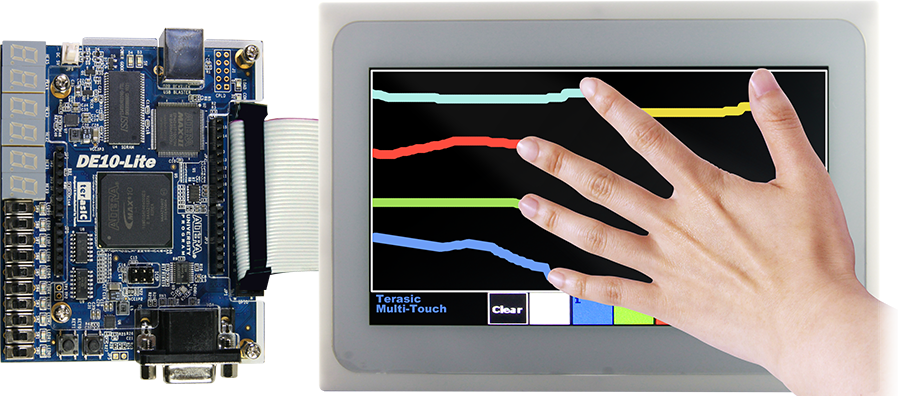
- Connect with MTL2
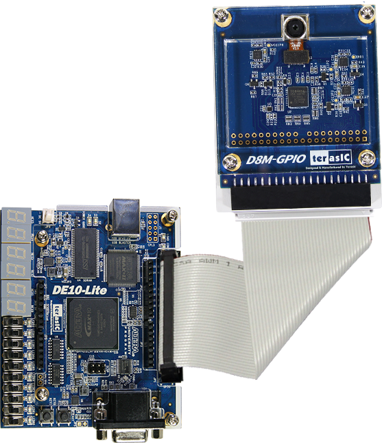
- Connect with D8M-GPIO
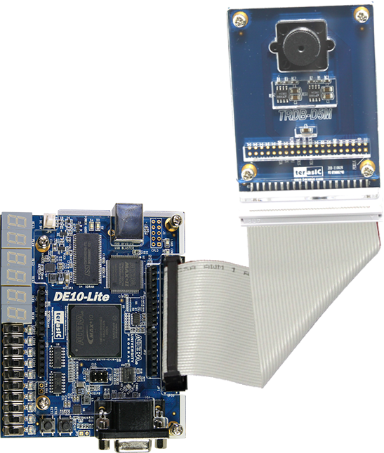
- Connect with D5M
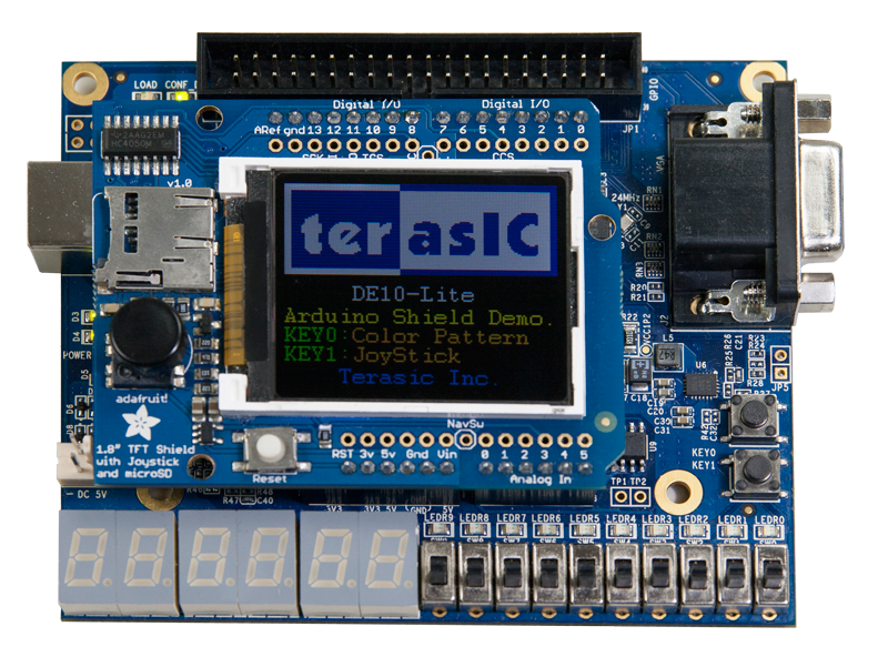
- Connect with Arduino Shield
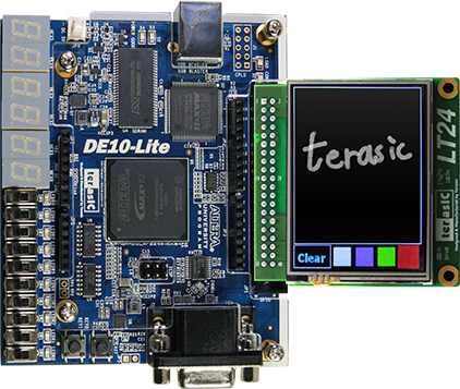
- Connect with LT24
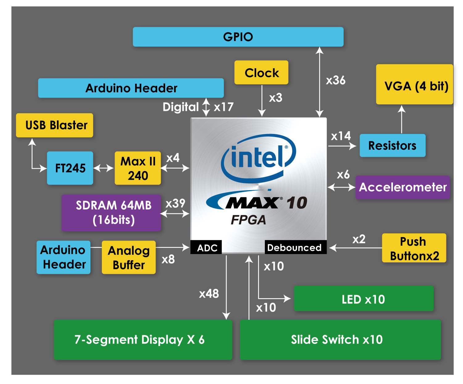
Block Diagram of the DE10-Lite Board
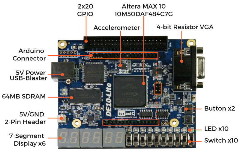
DE10-Lite Board Board Top-view
DE10-Lite Board Bottom-view
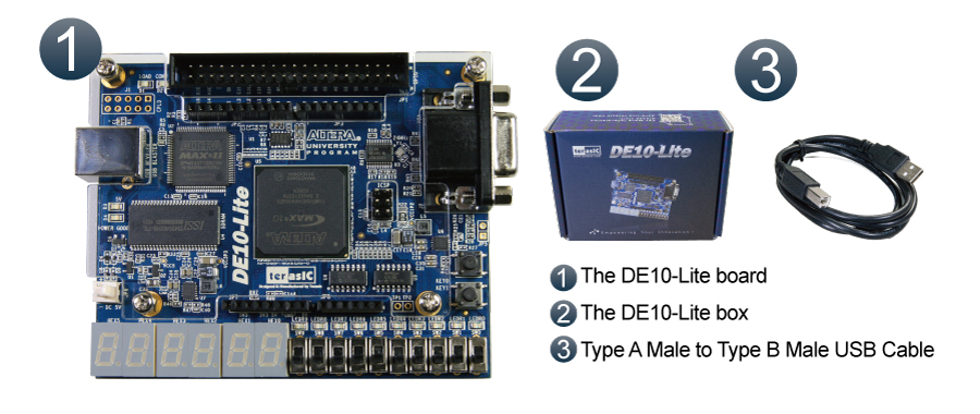
Package Include
- DE10-Lite Board
- DE10-Lite Box
- Type A Male to Type B Male USB Cable
Documents
Daughter Card Demonstrations
CD-ROM
| Title | Version | Description | Date | Download |
|---|---|---|---|---|
| DE10-Lite CD-ROM | 2.1.0 | 2020-06-05 | ||
| ControlPanel | 1.0.3 | 2018-05-10 | ||
| Quartus Download | 15.1.2 | 2016-06-21 |
More resources about IP and Dev. Kit are available on Intel User Forums.
Example Designs in System CD
- Factory Default Code
- SDRAM Test in Nios II
- SDRAM Test in Verilog
- VGA Pattern
- Accelerometer Level
- Accelerometer Rock
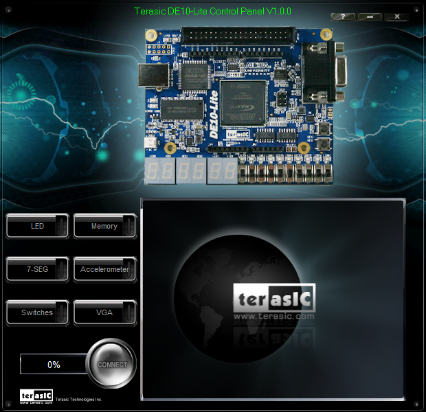
DE10-Lite Control Panel
Allows users to access various components on the DE10-Lite board from a host computer.
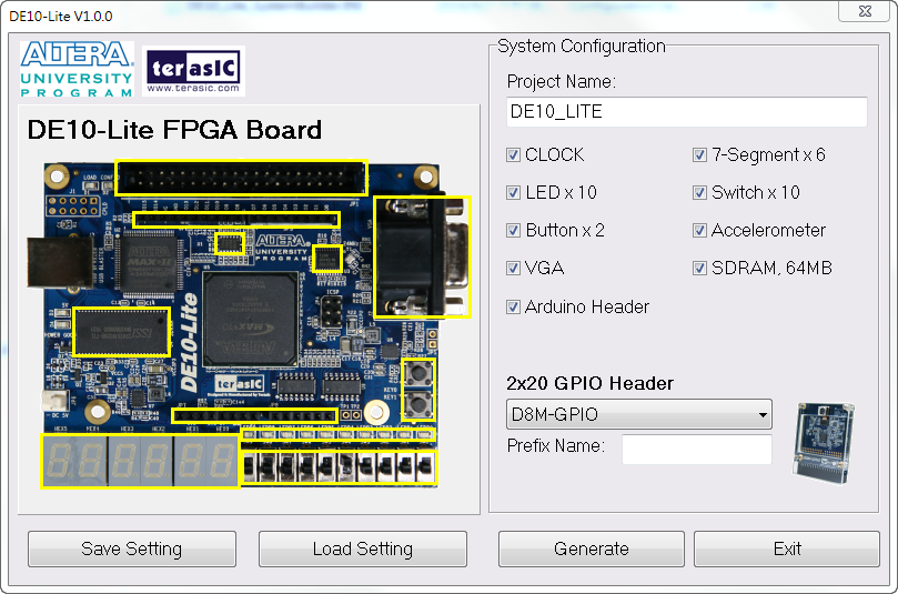
DE10-Lite System Builder
This tool will allow users to create a Quartus II project on their custom design for the DE10-Lite board with the top-level design file, pin assignments, and I/O standard settings automatically generated.